Frequency converter influence on the grid
Electromagnetic compatibility (EMC) means the ability of devices and technical systems to function normally under the influence of electromagnetic fields and conductivity interference on them and not to create unacceptable interference to other objects. When it comes to frequency converters, there are basically two types of negative influence of the converter on the surrounding equipment (Fig.1):
- Conductivity emissions into the network
- harmonics
- megahertz (radio-frequency, RF) interference
- Emissions radiated through air:
- through the converter housing
- from power and control cables
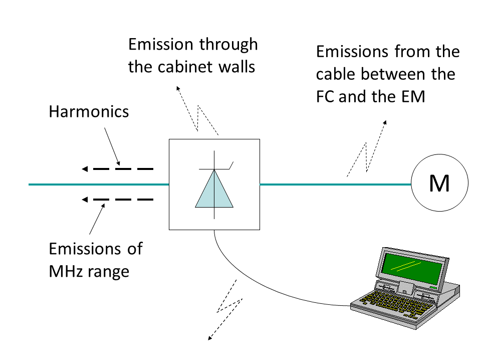
Fig. 1. Emissions from the drive system.
Harmonics created by the frequency converter
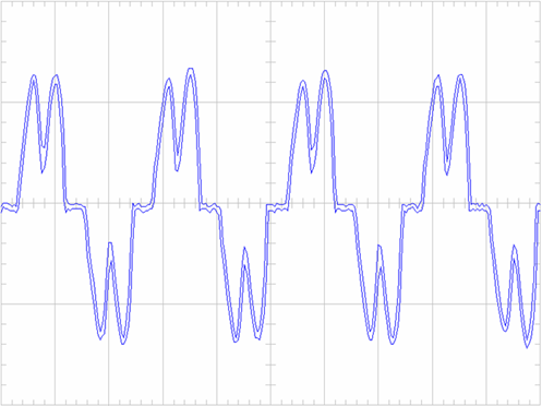
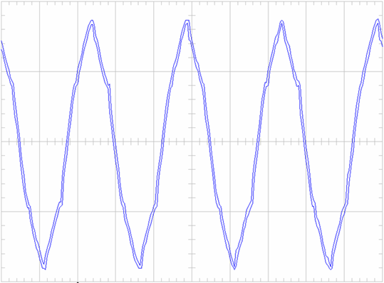
The frequency converter is a non-linear load for the supply network and the current and the voltage at FC input are not sinusoidal. Fig. 2 shows typical forms of current and voltage at the input of the 400 V, 75 kW FC with an uncontrolled 6-pulse rectifier. The current wave is usually distorted much more than the voltage.
 (a)
(a)
 (b)
(b)
Fig. 2. Waveforms of current (a) and voltage (b).
 (a)
(a)
 (b)
(b)
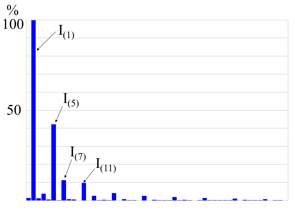
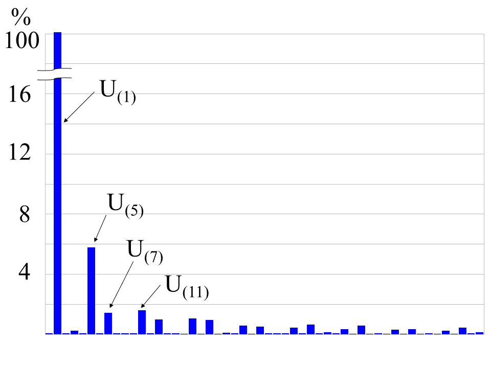
Fig. 3. Fourier transformation of current (a) and voltage (b).
Measures of current and voltage distortion
The common measure of the harmonic distortion of the current wave is "total harmonic distortion (current)" - THD(i):
A similar factor is used for voltage - THD(u):
For example, for the waveform in Fig.2 the values of and are 40.2% and 6.6%, respectively. Sometimes in the expressions for the sinusoidal distortion coefficients in the denominator the non-effective value of the first harmonic ( or ), but r.m.s. value ( or ).
Negative effects of harmonics
- Equipment misoperation and failure
- e.g. failure due to overheating of transformers, motors and cables, failure of capacitors because of resonance, failure due to insulation deterioration.
- Inconsistent meter reading
- Need for oversizing neutrals, transformers, generators
- Extra losses/Inefficiencies/power factor penalties
What defines how strong the distortion is
Level of distortion is defined by the topology of the FC and the used filters (if any) as well as stiffness of the grid. To define the «stiffness» of the supply grid, the short-circuit current is calculated by hypothetically placing short-circuit at the supply terminals. The stiffness of the supply must be calculated in relation to the load current, therefore, the stiffness is defined by a ration called short-circuit ratio (SCR): , where – fundamental frequency component of the load current.
The stiffer the grid will be (the higher the SCR) the more harmonics the FC is usually allowed to inject into the grid.
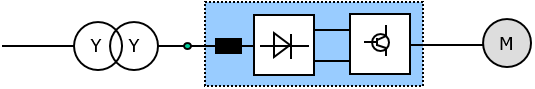
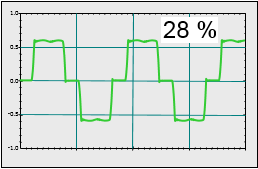
Influence of the topology and the filters is presented in a few diagrams below. Standard uncontrolled 6-pulse rectifier with a choke as the input filter (Fig.4,a) produced quite a lot of current distortion (Fig.4,b).
 (a)
(a)
 (b)
(b)
Fig. 4. 6-pulse rectifier with a choke; system topology (a) and current waveform with THD(i)=28% (b).
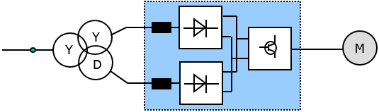
12-pulse scheme with 3-winding transformer (Fig.5,a) reduces harmonics injected into the grid (Fig. 5,b) compared to 6-pulse scheme with 2-winding transformer.
 (a)
(a)
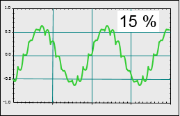 (b)
(b)
Fig. 5. Topology of the 12-pulse system (a) and current waveform with THD(i)=15% (b).
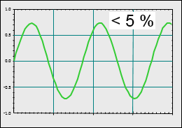
AFE converter provides lowest THD(i) (Fig. 6,b) but a bit higher THD(u) than 12-pulse scheme.
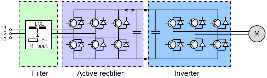 (a)
(a)
 (b)
(b)
Fig. 6. AFE converter with LCL filter (a) and the current waveform with THD(i)=5% (b).