Duties and overloads
If load of the mechanism is intermittent and follows a certain pattern, this load can be characterized by some standard duty and overload type. Some standard pattern according to IEC34 are presented in the chart (Fig.1). S1, S2 and S3 patterns contain only loads up to the rated load, while S4 patterns contains also overload, marked "D" (when the load is above the rated value it is called overload).
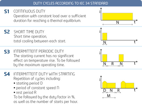 Fig.1. Standard duty cycles.
Duty is the ratio of the time at full load to the total time. In DriveConstructor the range to choose from is 50...100%. Duty cycle period is the time before the load pattern repeats itself. In DriveConstructor the range to choose from is 0,1...100 min.
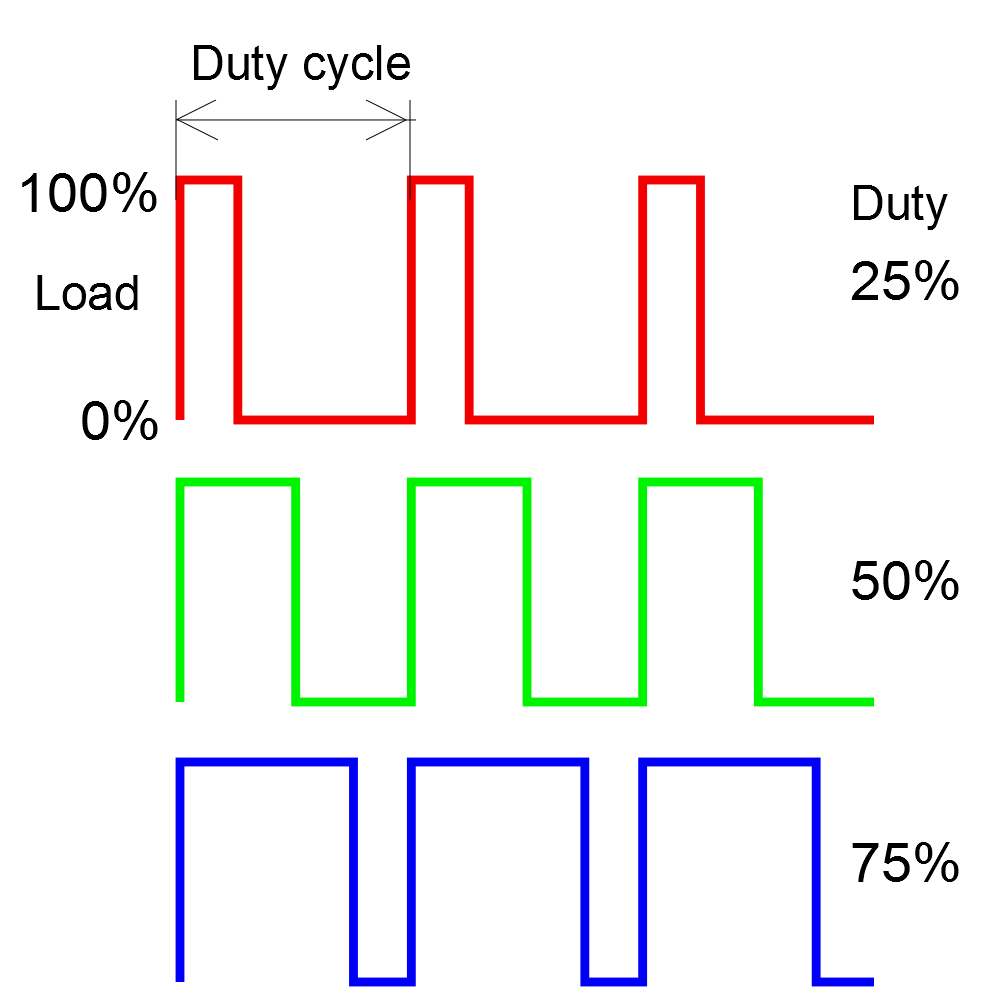 Fig.2. Duties of 25, 50 and 75%.
Both duties and overloads have similar thermal effect. When the equipment is loaded (state "ON" in Fig.3) the temperature inside the component goes up. When load is removed (state "OFF" in Fig.3) then the temperature decreases. The rate of the temperature increase or decrease is defined by thermal constant of this particular component.
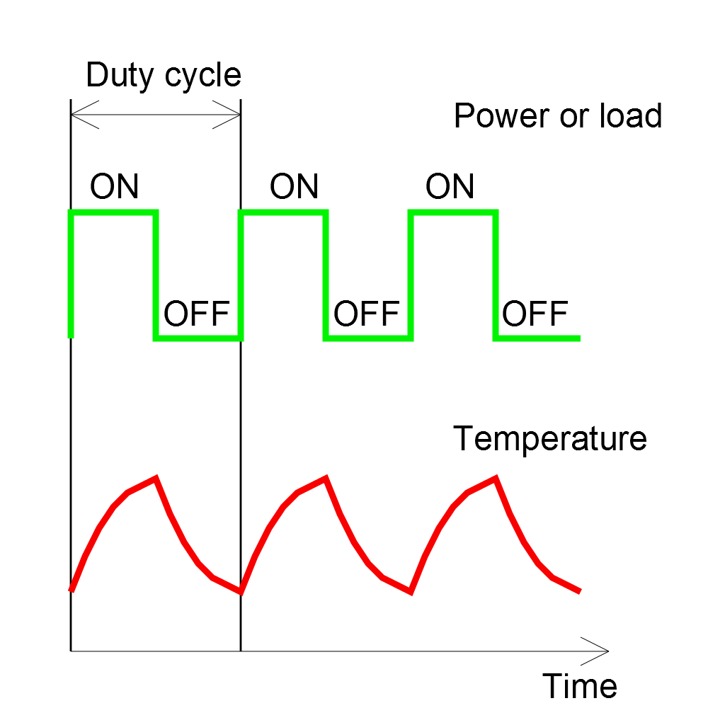 Fig.3. Duties and temperature inside the loaded component.
To illustrate how overloads are defined in DriveConstructor Fig.4 presents overload of 100%. The reference is rated load which is taken as 100%. The overload of 100% means the overload amplitude is 200%.
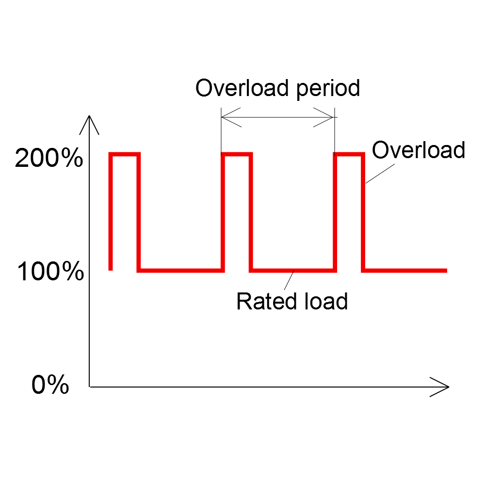 Fig.4. Overload of 100%.
Different components have different tolerance to overloads. Even different electric machines have different overload tolerance; induction machines can handle 200% overload amplitude, while PM machine usually will handle lower - maybe 150% amplitude (=50% overload).
The limits in the components are not only thermal, but can be for example saturation of magnetic cores in electric machines or maximum permissible current of the switches in the FC.
Machine can thermally absorb long overloads, converter - only short ones.