Inertia
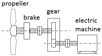
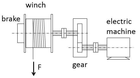
All moving (rotating) parts of a drive train are characterized with their own inertia. There can be calculated a combined inertia of several mechanically connected parts – for example “rotor + coupling + driven mechanism”. To calculate combined inertia of the drive train without gearboxes inertias of the drive train's parts are simply summed up. A gearbox changes the inertia in the system and, from the operation point of view the gearbox may play both a positive and a negative role. Possible system level considerations are presented below with the help of the four cases related to operation of a tidal turbine and a winch. The drive trains in the four cases include a gearbox, an electric machine and a brake (Fig.1).
 (a)
(a)
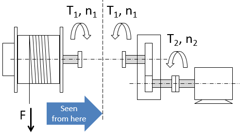
 (b)
(b)
Fig. 1. Mechanical drive trains for a tidal turbine (a) and a winch (b).
Case 1. Critical acceleration of a tidal turbine at grid loss
In case of grid loss the turbine should be braked. Before the mechanical brake is applied, the propeller will accelerate extremely fast if the system inertia is low. When analyzing the inertia in a system with a gearbox one could divide the train into two “parts” or “sides”: the “first” - where the force of the water stream is applied, and the “second” – which is counteracting the force. The gearbox usually belongs to the ”second” side. Since in our case the action is performed by the water acting on the propeller trying to accelerate it, therefore, it is useful to look at the system “from the propeller side” as in Fig.2.
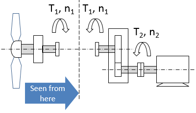
Fig. 2. Torques and inertia seen by the propeller.
When the electric machine (generator) is in “off”-state e.g. due to a failure and cannot produce any torque outbalancing the force acting on the blades, acceleration can be limited only by the dynamic torque, corresponding to the system inertia “seen” by the propeller. The dynamic torque is defined by the inertia:
.
The propeller “sees” the gearbox and the generator as a one whole with the total inertia of , where is moment of inertia of the propeller itself and i is gear ratio.
It can be seen that the gearbox plays a positive role as it increases the inertia “seen” by the propeller and as the consequence it increases the dynamic torque resisting the propeller acceleration: , where .
This positive effect is higher for higher gear ratio.
Case 2. Stream turbulence in normal operation of tidal turbine
Underwater waves hitting the blades create stresses on the elements of the mechanical drive train. Low system inertia “seen by the propeller” will be an advantage as it lets the generator “to give a slack” to absorb the “hit” by letting the propeller to accelerate a bit and then bring it back to the right speed. However, the torque that the accelerating blades will experience is the sum of the electromagnetic torque applied by the generator and the mechanical dynamic torque: , where the dynamic torque is .
Dynamic torque gets higher when the gear ratio increases. It will increase “stiffness” of the system and will lead to higher stresses on the mechanical components. Therefore, a gearbox with a high gear ratio plays a negative role.
Case 3. Accelerating and braking the winch with the electric machine
Permanent acceleration and braking is typical for example in active heave compensation winch deploying ROV, which is moving with the waves.
 (a)
(a)
 (b)
(b)
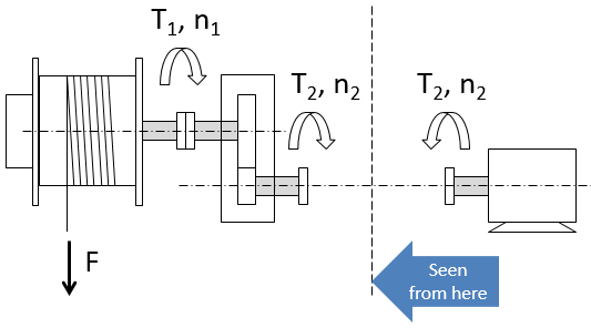
Fig. 3. Torques and inertia seen by the motor (a) and the winch (b).
When accelerating or braking the system, the electric machine, being the “actor” “sees” the winch and the gear as a whole (Fig.3,a). The machine should provide the torque high enough to overcome the total system inertia. The system inertia is made by the winch drum inertia “seen through the gearbox” and own inertia of the electric machine (rotor inertia): .
The winch drum inertia “seen through the gearbox” is given by the winch drum’s own inertia (defined by mass and radius of the drum) and the gear ratio i (taken in power 2): , where .
We assume that i>1 and electric machine speed higher than winch speed.
So, the total inertia the machine is to overcome when accelerating is
It means that when the gear ratio is high (order of 1:100) it is practically only the machine’s own inertia that matters. For acceleration and deceleration it is also beneficial to have low torque requirement for the machine, which is provided by the gearbox:
So, the gearbox plays a positive role.
Case 4. Winch braking when the electric machine fails
When the electric machine fails (e.g. short-circuit) the winch should be braked with the mechanical brake. Analyzing the problem it is correct to “see” the system from the winch side since the brake located at the winch drum is the “actor” applying the braking force (Fig. 3,b). The brake “sees” the gearbox and the machine as a whole with inertia equal to
“Dynamic” braking power is defined by the dynamic torque: , where .
The required braking power will be sizing the brake. So, the gearbox plays a negative role, increasing the inertia.
Conclusions
Having gone through the four cases we can conclude that there is always a trade-off between positive and negative sides and the system designer should look for the optimal gear ratio.
Note that parts of the gearbox will also always contribute to the inertia. We neglected gearbox’s own inertia and energy losses in the above for simplicity.