Filters
In many cases FC should be equipped with either input or output filters. Filters can help to solve various EMC issues on both grid side and machine side. However, the pay is extra size, weight, cost and losses. Some MV topologies do not require output filters. In DC it is possible to choose “choke” and “choke+RFI” for input filter and du/dt filter and sin-filter for output filter.
Output filters
SIN-filter
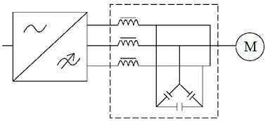
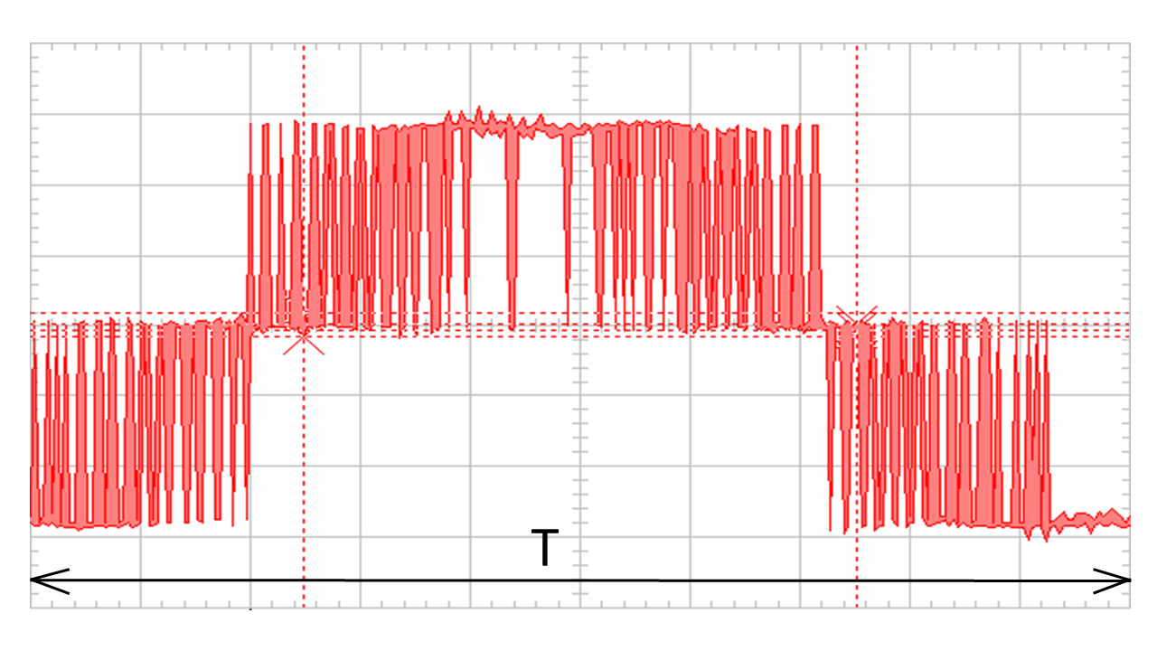
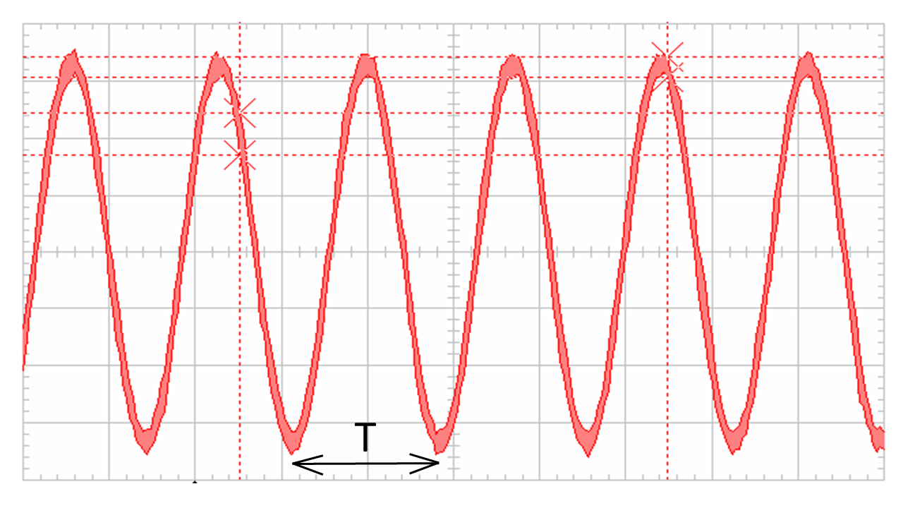
The LC filter, called the "sinus filter", "sine-filter" or "sin filter" (Fig. 1) is the most efficient filter in terms of turning the current and voltage waveforms that the FC produces into almost sinusoidal form. Fig. 2 shows an example of the effect of a sin-filter on the shape of the voltage waveform at the FC output. With the use of a sin-filter, virtually all the negative effects described in chapter FC influence on the electric machine> are eliminated, since the machine is powered by voltage and current with a shape very close to sinusoidal.
 (a)
(a)
 (b)
(b)
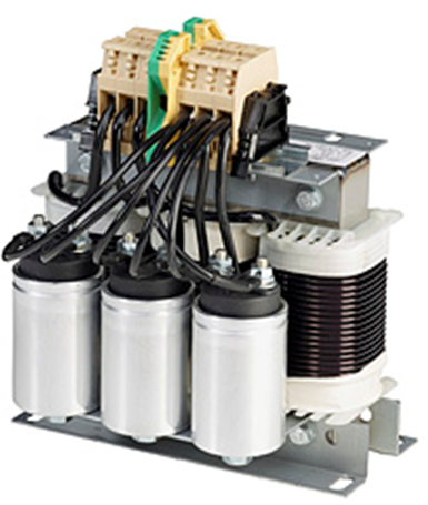
Fig. 1. “Classical” sin-filter topology (a) and product example (b).
 (a)
(a)
 (b)
(b)
Fig. 2. The voltage waveforms at the input (a) and at the output (b) of the sin-filter. Note different time span on the oscillograms.
Sin-filters have certain drawbacks (largely due to the high inductance value of its chokes):
- The voltage drop in the filter is 3-10%, depending on the manufacturer, the nominal power (current) of the filter and the frequency of the PWM.
- Losses of 0.5-2%. The more power, the lower the relative losses in the filter.
- Displacement of the field weakening point by 1-2 Hz towards low frequencies.
- Significant reduction (up to 20% or more) of the critical moment (overload capacity) of the machine.
Also it should be noted that the sine-filter is quite an expensive device. Its cost can be up to 30-40% of the cost of the FC (at low power - up to 50-70%).
du/dt-filter
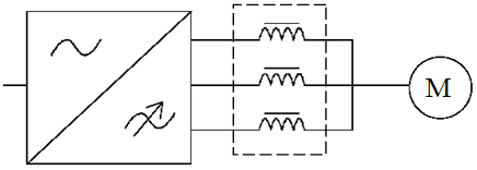
Structurally, the du/dt filter is a three-phase choke (Fig. 3,a), and from the point of view of the electric circuit theory it is a concentrated inductive resistance. The inclusion of inductance in the equivalent electrical circuit of the cable increases the wave resistance of the cable line and brings down the reflection coefficient. Thus, the voltage peaks at terminals decreases.
 (a)
(a)
 (b)
(b)
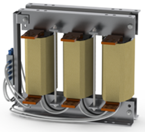
Fig. 3. “Classical” du/dt-filter topology (a) and product example (b).
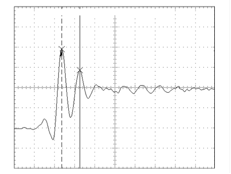
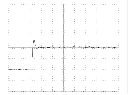
However, the main purpose of du/dt-filters is to eliminate du/dt-effect, i.e. decrease in the rise time of the voltage pulse. In addition, due to the inertial properties of the inductance, the filter also reduces the voltage surge at the leading edge of the pulse (Fig.4). The length of the cable is 30 m. Note different rise time: dt=220 ns, dt=820 ns.
 (a)
(a)
 (b)
(b)
Fig. 4. Voltage pulses at the machine terminals without du/dt-filter (a) and with a filter (b).
Common recommendations on the use of du/dt-filters and other measures
To reduce the overvoltages, du/dt-effect and bearing currents, a whole complex of measures is often applied, including both recommendations to machine manufacturers, and the use of various filters, special cables, etc. The measures depend in particular on the voltage level of the mains and on the power (size) of the machine. Different drive manufacturers can offer different measures. One example is presented in the table:
| < 100 kW | >= 100 kW | >= 350 kW | |
|---|---|---|---|
| Ur<=500 V | Standard machine | Standard machine + isolated N-bearing | Standard machine + isolated N-bearing + ferrite rings |
| Ur<=600 V | (Standard machine + du/dt-filter) or Reinforced insulation | (Standard machine + du/dt-filter) or (Reinforced insulation + isolated N-bearing) | (Standard machine + isolated N-bearing + du/dt-filter + 1 ferrite ring) or (Reinforced insulation + isolated N-bearing + ferrite rings) |
| Ur<=690 V | Reinforced insulation + du/dt-filter | Reinforced insulation + du/dt-filter | Reinforced insulation + isolated N-bearing + du/dt-filter + 1 ferrite ring |
Grid filters
Chokes
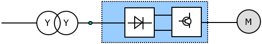
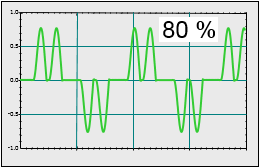
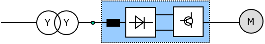
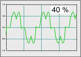
Influence of presence of the choke and its size on the harmonics injected into the grid is presented in Fig.5 and 6. The graphs show current waveform and the value of current distorsion THD(i) as % of nominal current at full load.
 (a)
(a)
 (b)
(b)
Fig. 5. 6-pulse rectifier without any choke (a) and current waveform for this topology (b).
 (a)
(a)
 (b)
(b)
 (c)
(c)
Fig. 6. 6-pulse rectifier with a choke (a) and current waveforms for small choke (b) and big choke (c).
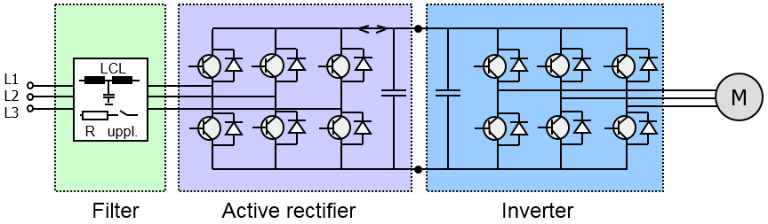
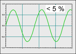
LCL filter
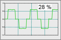
FC with LCL filter between FC and the grid is presented in Fig.7,a. Current waveform is very close to sinusoidal as can be seen in Fig. 7,b.
 (a)
(a)
 (b)
(b)
Fig. 7. Topology (a) and current waveform (b).
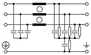
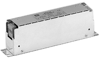
EMC filters
EMC filters (Fig.8) is destined for emission reduction in MHz range. Example of the effect is presented in Fig.9.
 (a)
(a)
 (b)
(b)
Fig. 8. EMC filters: topology (a), AC side filter product example (b).
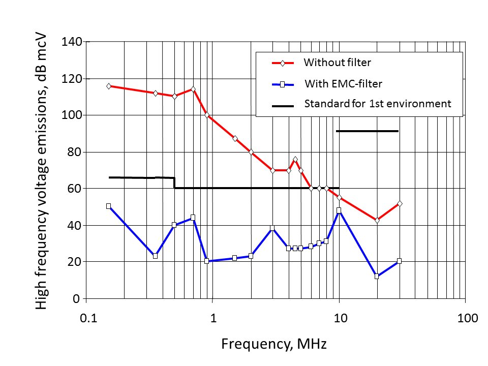
Fig. 9. Effect of use of EMC-filter.