Frequency converter influence on the electric machine
High frequency effects
Voltage rise time of IGBT can be within 0.1-0.2 microseconds. When powering the FC from the 400 V mains, the voltage in the DC link is about 540 V, so the rate of voltage rise in the IGBT can be up to 5 kV/μs. Influence of the sequence of pulse fronts with du/dt of 5 kV/μs on the system "FC-cable-machine-reducer-driven mechanism" is in many ways similar to the action of a sinusoidal voltage of the same amplitude, but with a frequency of the order of several megahertz. That is why the negative effects caused by the high switching are often called "high-frequency effects". The HF effects result in:
- Increased losses in windings and core of the machine due to non-sinusoidal voltages and currents
- Ageing and degradation of insulation, shorter lifetime of the insulation
- Degradation of bearings
The effects affecting the insulation and the one affecting the bearings are briefly presented below.
Travelling waves and overvoltage
In practice, the length of the cable between the FC and the machine can reach hundreds of meters and even up to a few kilometers. Due to the difference in impedance of the cable and the machines winding , voltage pulses get reflected from both ends of the cable. As the result, there appear waves travelling between the FC and the machine. At different instants of time, waves can either compensate each other (when pulses have different polarity) or add up (when polarity is the same). When the direct and reflected waves are combined, as shown in Fig. 1, the total pulse at the terminals of the machine can reach the value at which the insulation may break down.
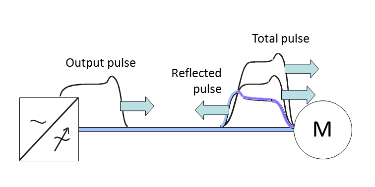
Fig. 1. Superposition of voltage pulses at the terminals of the machine.
One way to estimate the peak voltage at the terminals of the machine with allowance for wave superposition is , where is the amplitude of the voltage pulses at the converter output, equal to the voltage in the DC link. When the cable gets longer, decreases. In practice is within .
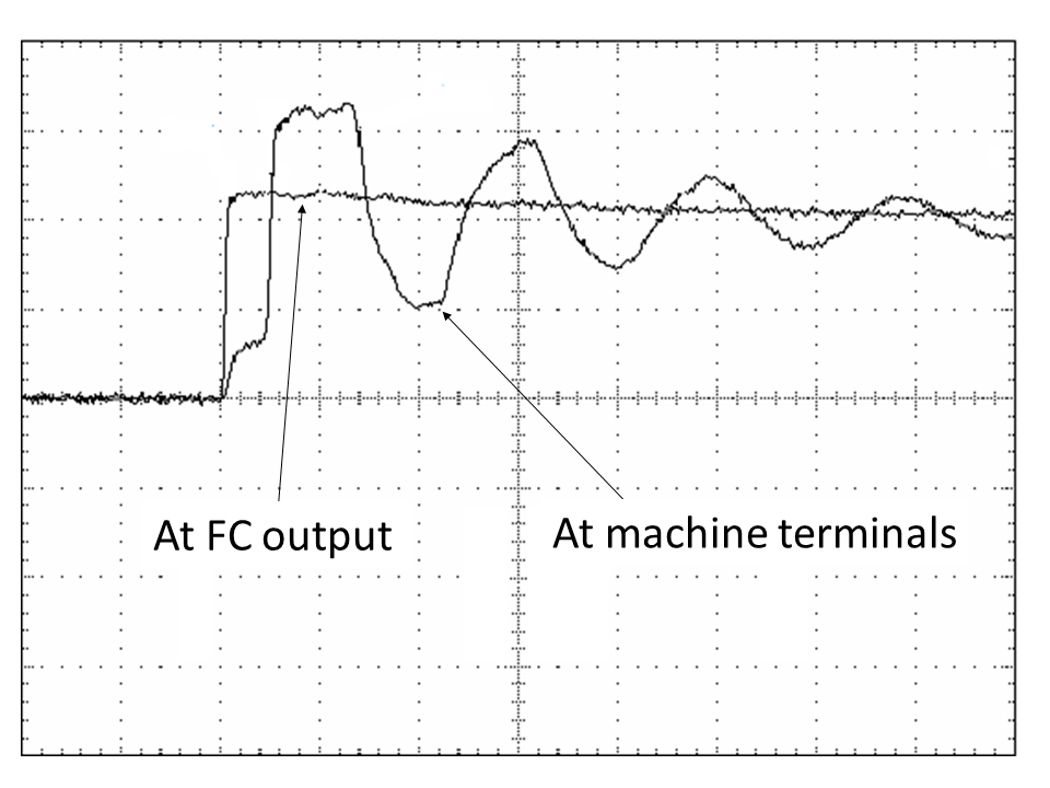
Fig. 2,a shows the measured voltage at the output of the FC and at the terminals of the machine (only part of the pulse is shown). For clarity, the impulses are superimposed on each other. The effect of superposition of forward and backward waves on the terminals of the machine resulting in voltage oscillations is obvious.
 (a)
(a)
 (b)
(b)
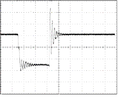
Fig. 2. Voltage pulses: the leading edge of the pulse at the output of the FC and at the terminals of the machine (a), both edges of the pulse at the terminals of the machine (b).
du/dt-effect
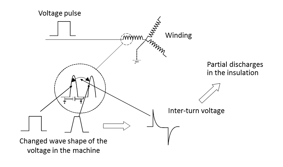
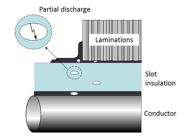
Sharp edges/fronts of the PWM pulses and capacitances in the winding lead to uneven voltage distribution inside the winding and create inter-turn voltage spikes as shown in Fig 3,a. This leads to partial discharges in the insulation (Fig.3,b). Constant partial discharges lead to aging of insulation and subsequent destruction (breakdown).
 (a)
(a)
 (b)
(b)
Fig. 3. du/dt-effect: origins (a) and consequences (b).
Bearing currents
The PWM modulation of the output voltage leads to a common-mode (CM) voltage. In Fig. 4 switching pattern is shown, and it can be observed how the common-mode (CM) voltage is generated. This voltage is obtained by adding the three voltages resulting from the three inverter legs. Having the DC-link mid-point as a reference, the voltages Va, Vb and Vc can either be +Vdc/2 or –Vdc/2, where Vdc is the DC-link voltage. As a result, depending on the state of the switches, the common mode voltage can take one of the values ±Vdc/2 and ±Vdc/6.
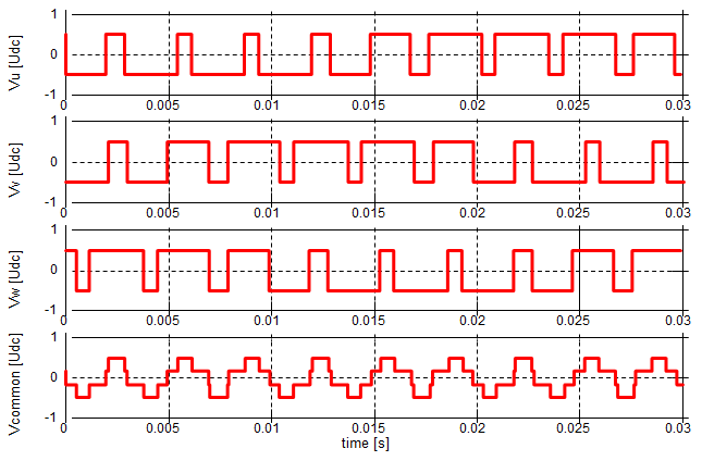
Fig. 4. Common-mode voltage.
CM voltages lead to appearance of CM high-frequency currents flow through complex circuits/paths some of which are presented in Fig.5. The HF currents circulating through the bearings of the machine (called “bearing currents”) can lead to premature bearing failures. Another example of the negative impacts is HF leakage currents through ground cables which can interfere with control cables.
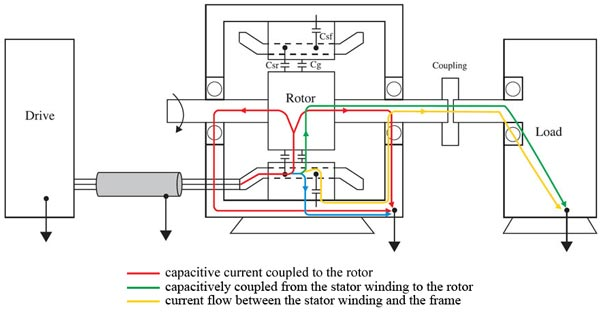
Fig. 5. The paths for HF currents.