Sizing principles
Main principles of the component choice
Some parameters/features of the components, such as type or topology of the component, its protection class, cooling methods, etc can be simply set by the user. However, there are many parameters which cannot be set freely for many of the components since the parameters are dependent on the parameters of other components in the drive train.
Electric machine, being an electro-mechanical converter, must be selected based on both mechanical parameters (torques and speeds) and electrical parameters (voltages and currents) - see Fig.1.
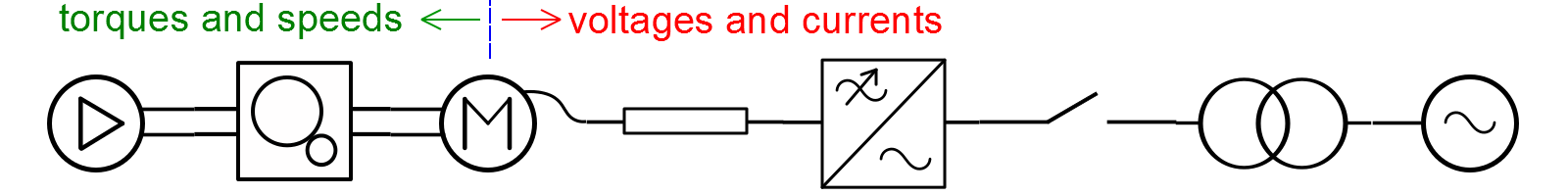 Fig.1.
For the system part between electric machine and the grid the components are selected according to the electrical parameter - voltages and currents.
- For systems without transformers:
- electric machine’s voltage and current must match voltage of the frequency converter
- frequency converter voltage must match voltage of the grid
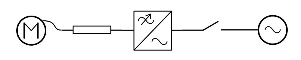 Fig. 2.
- For systems with transformer between the grid and the frequency converter:
- electric machine’s voltage and current must match voltage and current of the frequency converter
- frequency converter voltage and current must match LV-side voltage and current of the transformer
- transformer HV-side voltage must match voltage of the grid
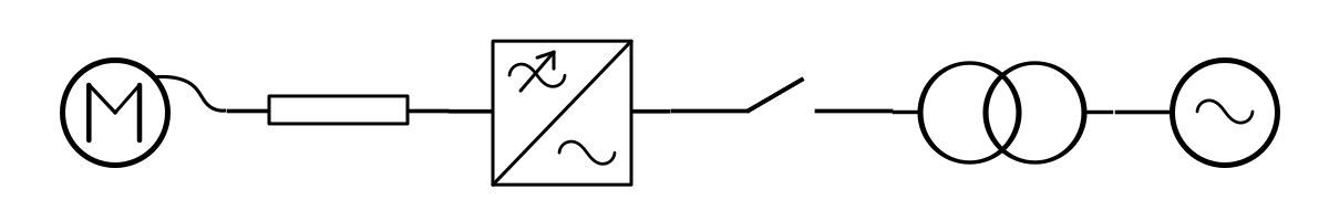 Fig. 3.
For the system part between the electric machine and the mechanism the components are selected according to mechanical parameters - torques and speeds.
- For systems without gearbox:
- electric machine’s torque and speed must match torque and speed of the mechanism
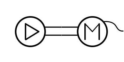 Fig. 4.
- For systems with gearbox:
- gearbox torque and speed must match torque and speed of the mechanism
- electric machine’s torque and speed must match torque and speed of the gearbox
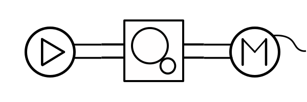 Fig. 5.
Matching the torques
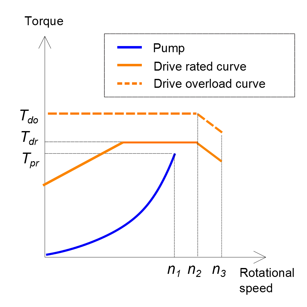
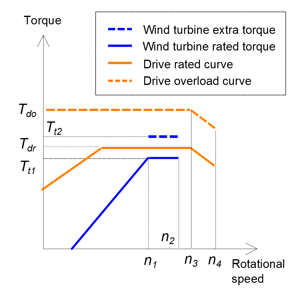
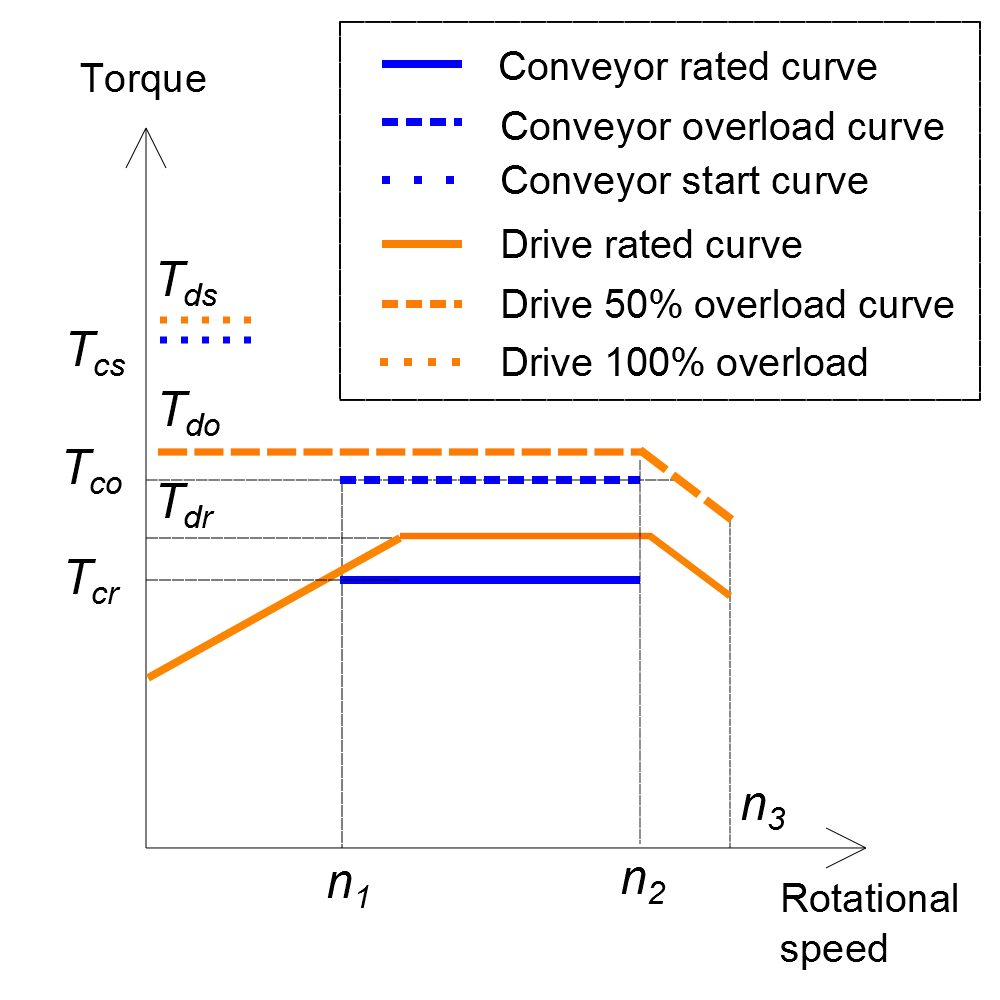
All points of the drive system’s rated torque curve should be higher than those of the driven mechanism as shown in Fig. 6 for the different mechanisms; pump (Fig. 6,a), wind turbine (Fig. 6,b), conveyor (Fig. 6,c,d) and winch (Fig. 6,e,f). Note than overload curves of the drive system should be above the overload curves of the mechanisms.
 (a)
(a)
 (b)
(b)
 (c)
(c)
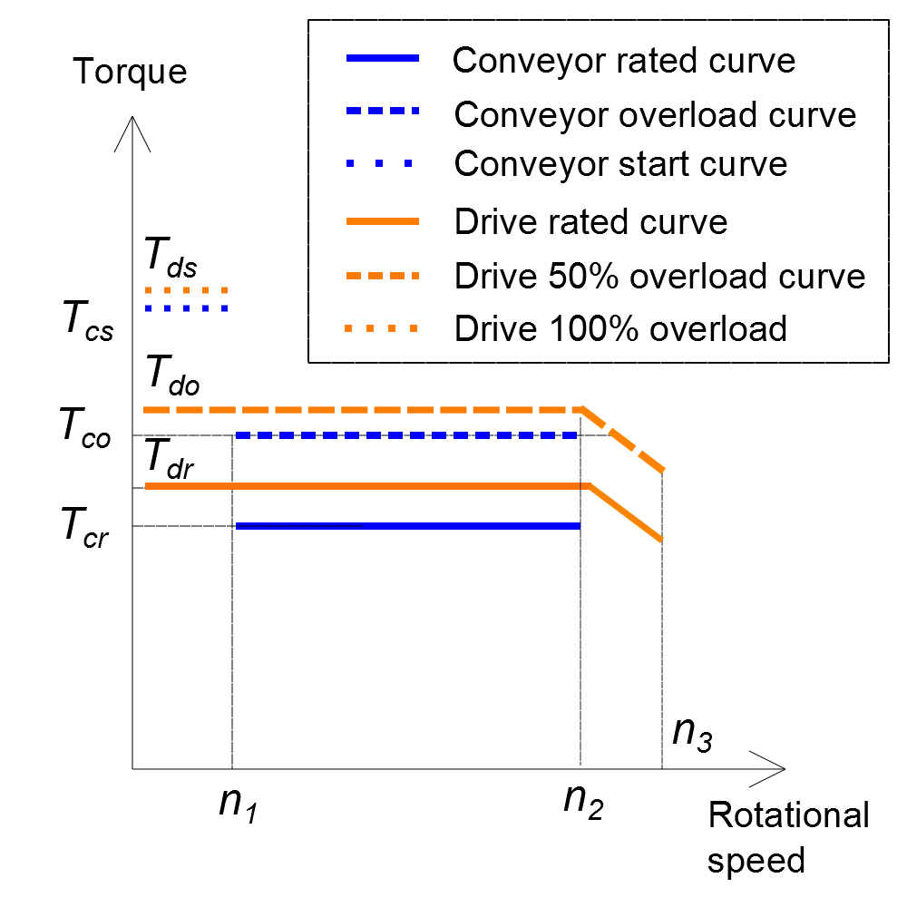 (d)
(d)
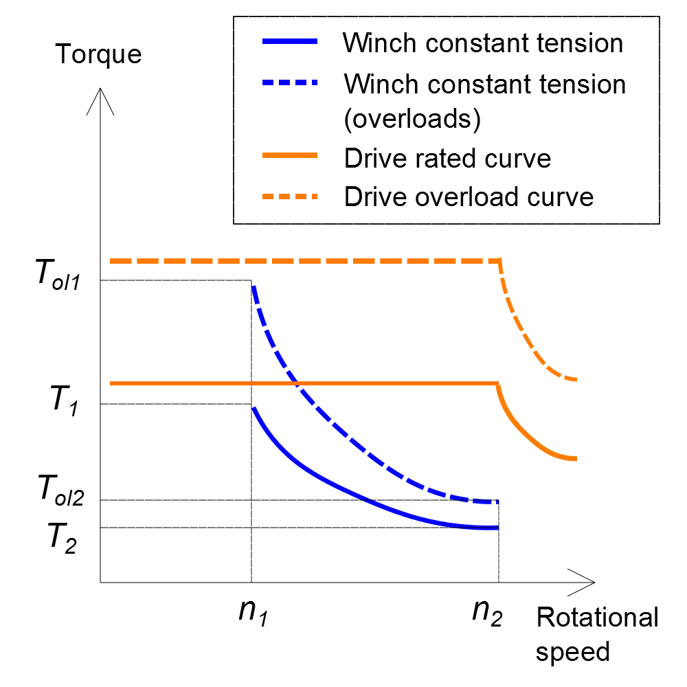 (e)
(e)
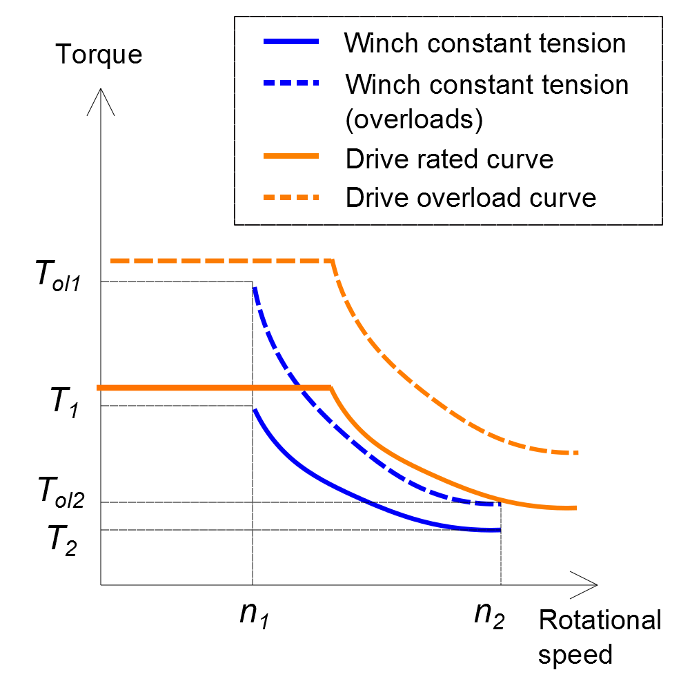 (f)
(f)
Fig. 6. System curves vs load curves for various mechanisms/application.
When we consider the power-speed relationships the striking difference between the constant-torque and fan-type load is underlined. If the motor is rated for continuous operation at the full speed, it will be very lightly loaded (typically around 20%) at half speed, whereas with the constant torque load the power rating will be 50% at half speed.
Difference of the algorithms for motor mode and generator mode
In motor mode we start from the driven mechanism, e.g. pump or conveyor, define its rated torque (which is load for the motor) and based on this data we choose the motor. If there is a gearbox between the mechanism and the motor, then the load torque at the motor shaft is calculated as [load torque]/[gear ratio]. In generator mode we start from the grid side and go down to the generator and gearbox, if any.