Energy saving with the help of VSD
More than 80% of the world's population of electric motors drive the mechanisms with a quadratic load characteristic - pumps, fans and compressors. Centrifugal pumps, being probably the most popular pump type, are used almost everywhere - nearly in all industries and utilities. Operation of centrifugal pump at variable speed usually demonstrate impressive energy savings compared to constant speed operation. The way of achieving the savings can be demonstrated for a basic water supply system shown in Fig. 1.
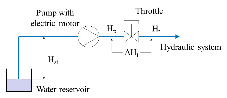
Fig. 1. Water supply with throttle regulation.
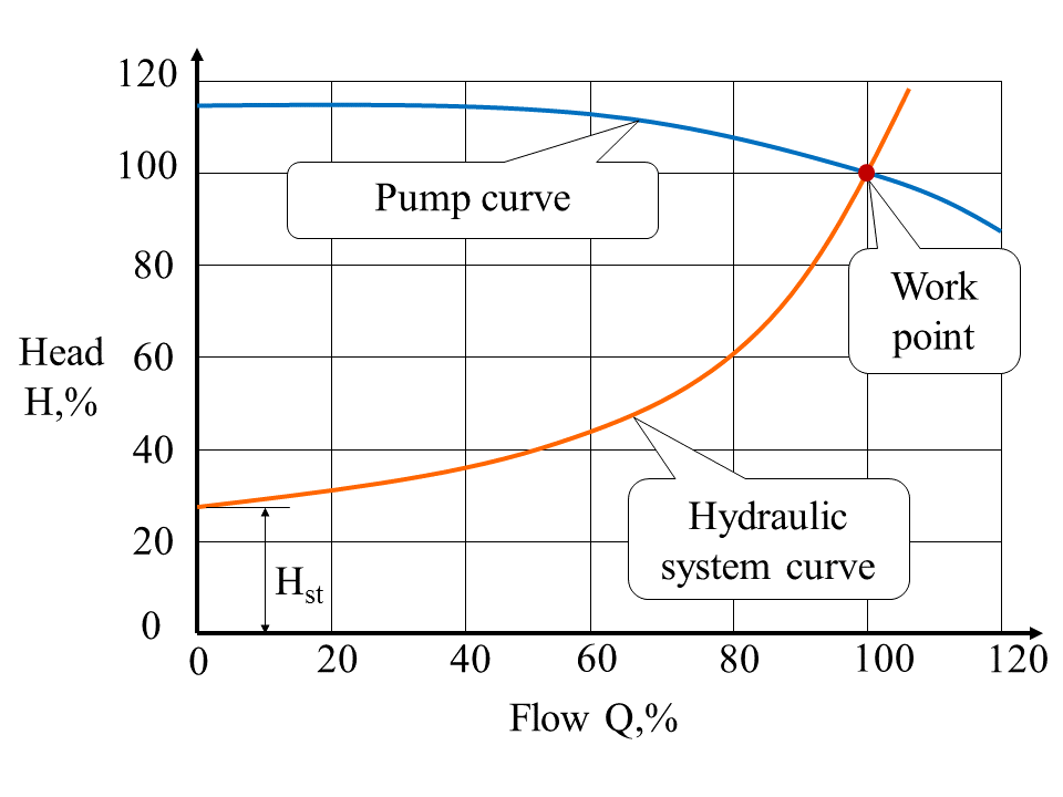
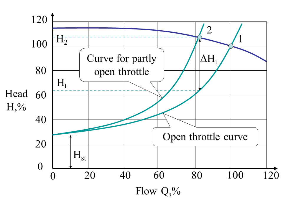
The height of the pump axis above the level of the water reservoir ("lift height") is called the static head . When rotational speed of the impeller of the pump is not regulated, a throttle (valve) is installed at the pump outlet, which can change area (cross-section) of the water passage to regulate the volume of the water supplied to the hydraulic network and the pressure in the network. The characteristic of the pump is determined in the coordinates of the head-flow H-Q. With the throttle fully open (Fig. 2a), the head and the flow are nominal (100%) and the pump's operating point is at the intersection of its own characteristic and the hydraulic network's (system's) characteristic. If it is required to set the flow below , the throttle partially closes and the characteristic of the hydraulic network shifts upwards (Fig. 2b). Accordingly, the operating point moves from "1" to "2". The new flow rate (Q = 82%) corresponds to a new head (H = 64%) in the network after the throttle, which is defined as the head difference at point "2" and the head drop ΔH:
.
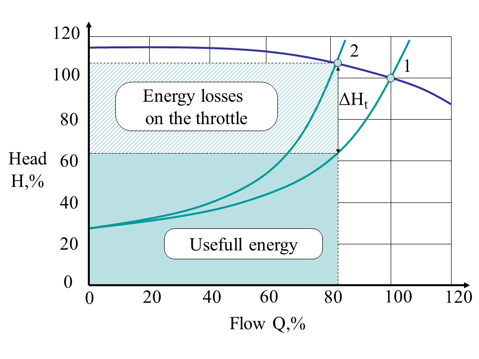
The disadvantage of the flow and head regulation by the throttle (called "throttling") is the energy loss at the throttle. The graphically useful energy and the energy lost on the latch can be represented by rectangles in Fig. 2c. It can be seen that even with not deep regulation of the pump flow (Q = 82% of the nominal value), the throttle losses make up more than 40% of the power.
Another problem of throttling is reduced efficiency of the pump when the pump's operating point is shifted from the rated due to the change in the performance of the hydraulic network (the throttle is part of the network).
 (a)
(a)
 (b)
(b)
 (c)
(c)
Fig. 2. Throttle control.
The power on the pump shaft is determined by the following expression:
,
where P is in kW, g is gravity ( ), is density of the pumped fluid in , is efficiency of the pump, h is head in m and q is flow in .
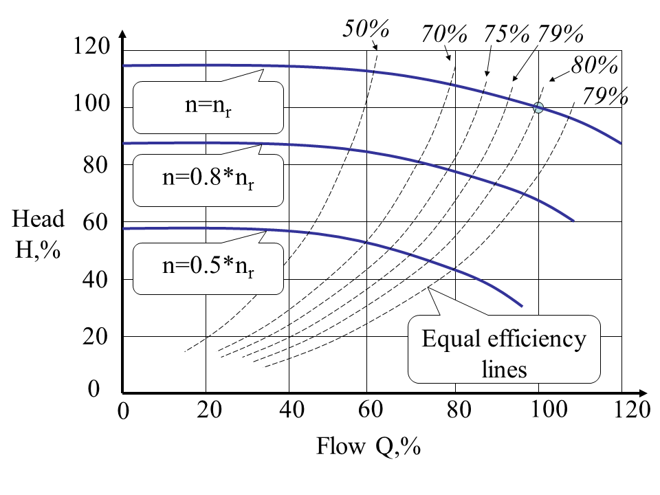
Thus, lower efficiency of the pump lead to increase power consumption. Fig. 3 shows the efficiency map of the pump (lines of equal efficiency).
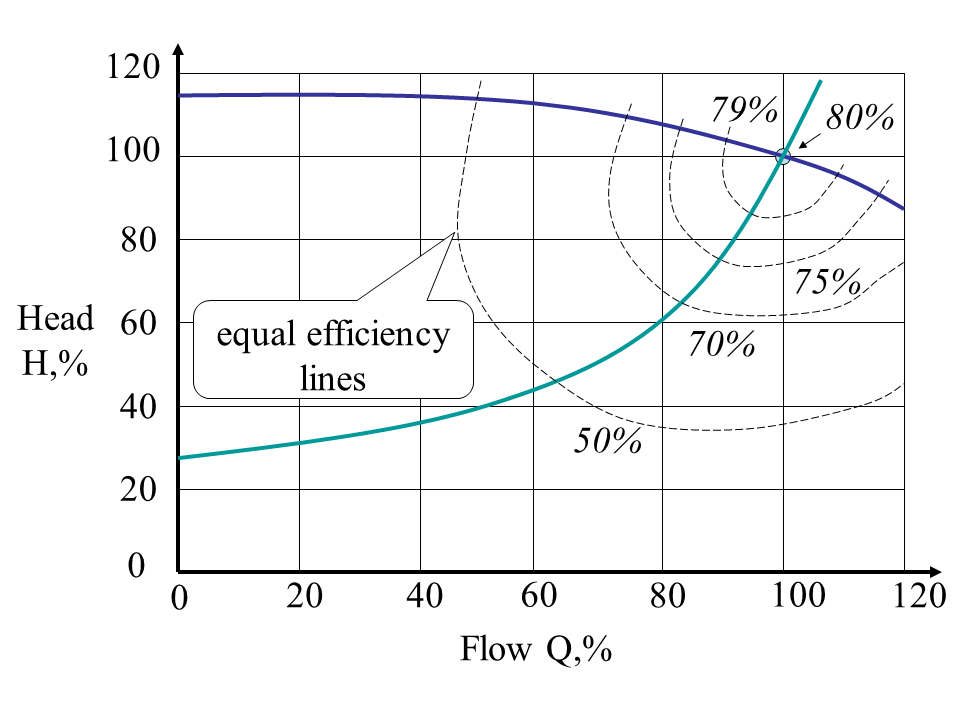
Fig. 3. Pump efficiency.
When adding the frequency converter to the motor driving the pump, the throttle can be permanently set to the fully open position. Head and flow control is performed by changing the rotational speed of the pump's impeller. Typically, a system with pump speed control operates in a closed loop on the feedback signal from the pressure sensor (Fig. 4).
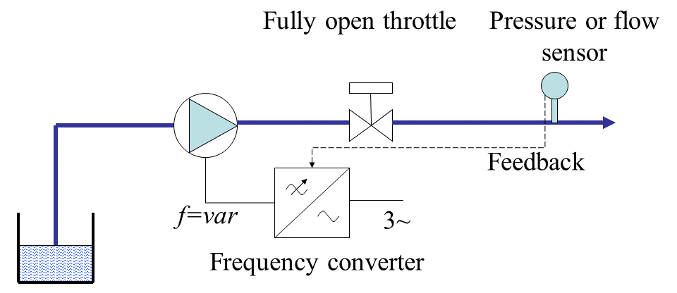
Fig. 4. Water supply FC control.
When the pressure in the network drops below by a value set by the operator, which indicates an insufficient flow, the inverter automatically increases the pump speed, which increases the flow rate and the pressure. Likewise, when the pressure rises above a preset value, the flow rate needs to be reduced - this is done by reducing the pump's speed.
 (a)
(a)
 (b)
(b)
 (c)
(c)
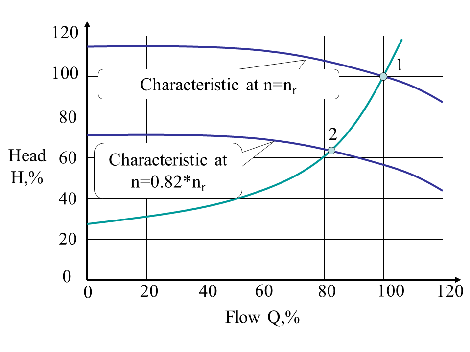
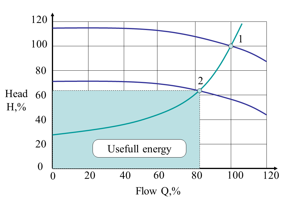
Fig. 5. Impeller speed regulation.
In contrast to the throttle control, when the displacement of the operating point during regulation was effected by changing the characteristics of the hydraulic network (the throttle is part of the network), in the event of a change in the speed of rotation of the impeller, the pump characteristic H-Q is shifted. Fig. 5a shows the displacement of the characteristics of the pump, and the operating point of the process with a decrease in speed from n to 82% of n. Since the valve is fully open, there is no loss on it and all the hydraulic energy generated by the pump is useful (Fig. 5b). It is noteworthy that when the pump speed is regulated and the corresponding displacement of its characteristic, the operating point is constantly in the zone of maximum efficiency (Fig. 5c).