What is a drive system?
Architecture
The drive train in Fig.1 includes all the components available in DriveContructor:
- driven mechanism (pump in this case),
- gearbox,
- electric machine,
- cable,
- frequency converter,
- circuit breaker,
- transformer, and
- the grid.
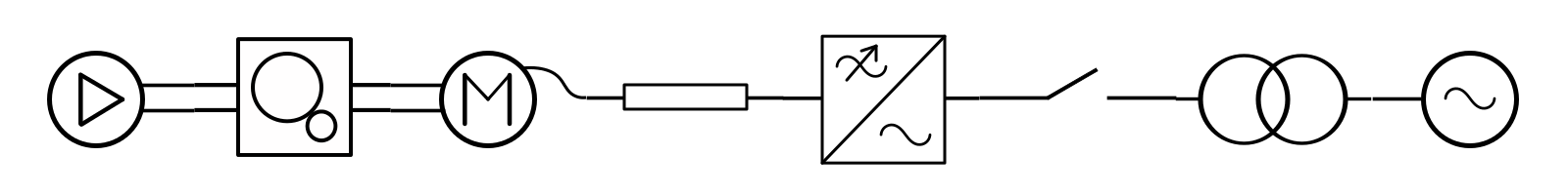
Fig.1. System with all available components.
In real life there can be used e.g. softstarter or Y/D-starter instead of the frequency converter. The gearbox, the transformer or both, can be omitted. Also numerous topologies with parallel branches are used. However, in DriveContructor we focus on the single branch topology like in Fig.1.
Characteristics
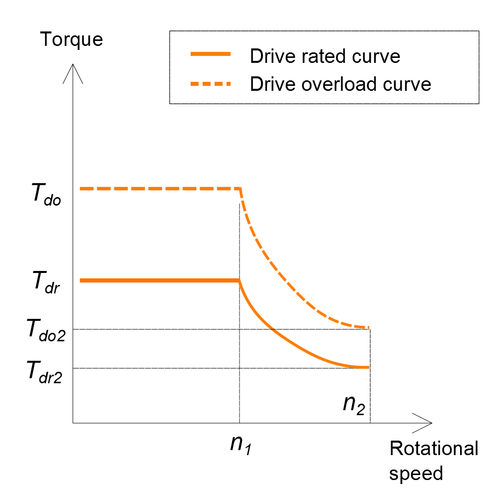
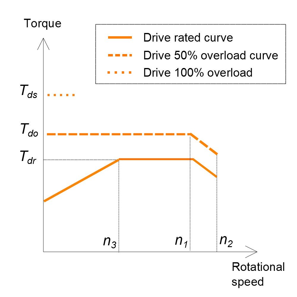
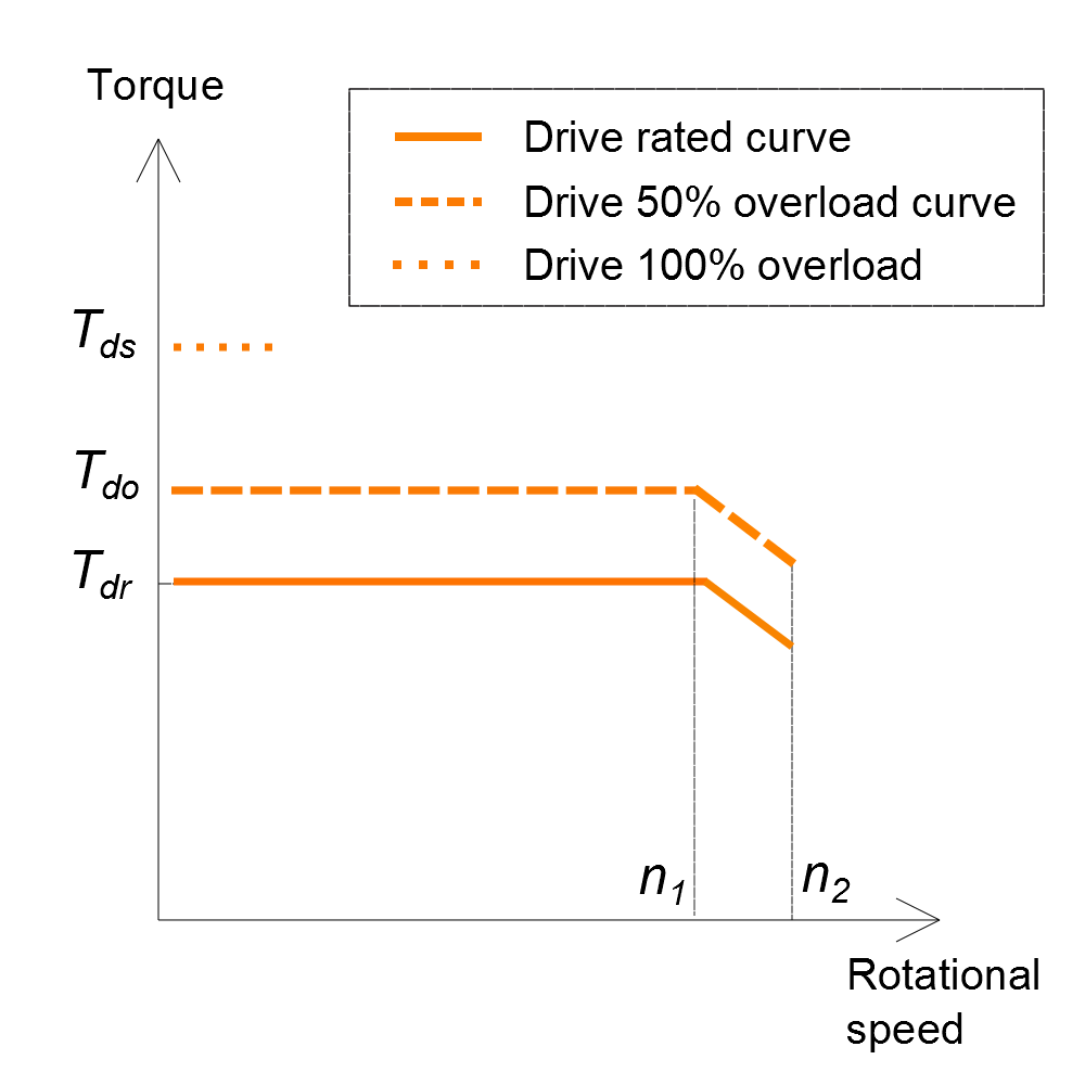
In general any drive system can be characterized by torque curves like for example the ones shown in Fig. 2(a-c), where rated torque curve and overload torque curve are shown. The plot area to the right of the speed is called “field-weakening” area, which can be longer or shorter depending usually on mechanical constraints. If machine with self-ventilation is used the torque curves will be like in Fig. 2(b). One can see the rated torque curve goes down in the area of low speeds () – this is due to reduced cooling capability of the shaft mounted fan. Also note, that there can be more than one overload curve. For example in Fig. 2(b) and Fig.2(c) there is 50% overload which can be permitted longer and 100% overload, permitted shorter. Curves in Fig.2(c) are for forced-ventilated or water-cooled machine as torque curves are horizontal in the speed area below .
 (a)
(a)
 (b)
(b)
 (c)
(c)
Fig.2. Drive system curves.