 DriveConstructor
Power cables
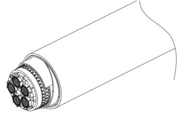 Fig.1. Medium voltage cable.
Cable parameters
Voltage
In DriveConstructor voltage rating of a cable is being chosen automatically according to the voltage at the electric machine terminals.
Length
We limit the possible cable length to 5 km, so the range to choose from is 0 to 5000 m
Cable cross-section
Cables are produced with standard cross-sections of their phase conductors. We can choose from the row: 0.5, 0.75, 1, 1.5, 2.5, 4, 6, 10, 16, 25, 35, 50, 70, 95, 120, 150, 185, 240, 300, 400, 500, 630, 800 and 1000 .
Conductor material
In DriveConstructor, as well as in the real life, the choice should be made between copper and aluminum cable. Some arguments are presented below.
Considering weight and size
For the same conductivity the weight of an aluminum cable will be only 54% of the weight of a copper cable, but the cross-section of the aluminum cable will be higher than that of the copper cable by 56%. So the choice will be a greater cable cross-section or a higher cable weight. Copper cable is thinner but heavier.
Considering cost
Generally speaking, aluminum cable will be cheaper. However, copper cable is more ductile and less susceptible to electrical contact problems. Due to its smaller cross-section, the copper cable will also be easier to install as the stiffness of the cable depends on the square of the cross-sectional area and thus on the fourth power of the diameter. So one should take into account the extra cost and effort involved in installing the less pliable aluminum cables.
Number of runs
The surface of the cable increases not proportionally (actually slower) with increase of the cable's cross-section, therefore, for a thicker cable heat dissipation is less intensive and the current density should be decreased compared to thinner ones. So, in some cases it may be more economical to have two or more parallel thin cables (two or more "runs") with higher current densities than one big cable with lower current density. In DriveConstructor it is possible to choose number of runs from the following options: "auto", 1, 2, 4. When "auto" is chosen, DriveConstructor will calculate optimal number of runs automatically.
DFIM cable-section approximation
The power circuit of a DFIM wind-turbine system has two parallel paths: one connected to the stator winding and one connected to the rotor winding (Fig. 2). The cable length entered in DriveConstructor is the physical stator-cable route. The stator voltage drop is calculated using that physical length.
To approximate the additional rotor-circuit cable, installed cable quantity and price are multiplied by 1.33. Resistive loss is not proportional to installed quantity: under the simplified equal-resistance assumption and 30% rotor-current fraction, combined stator and rotor loss is multiplied by . The rotor circuit is not modeled as a separate cable candidate.
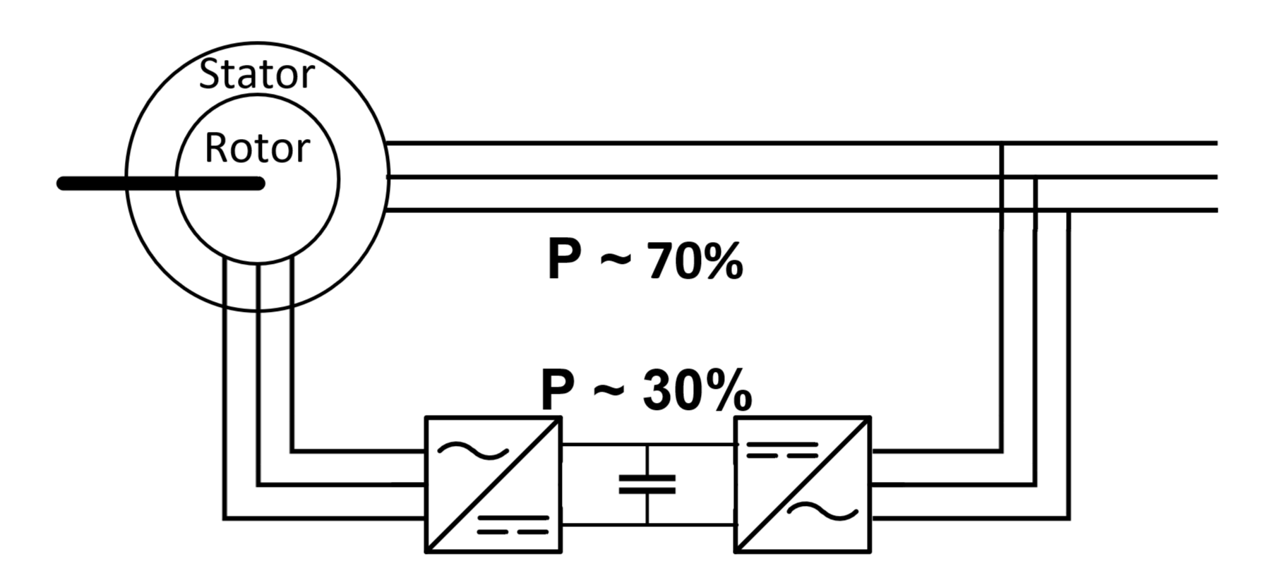 Fig.2. Stator and
rotor cable sections from DFIM system.
Fig.2. Stator and
rotor cable sections from DFIM system.